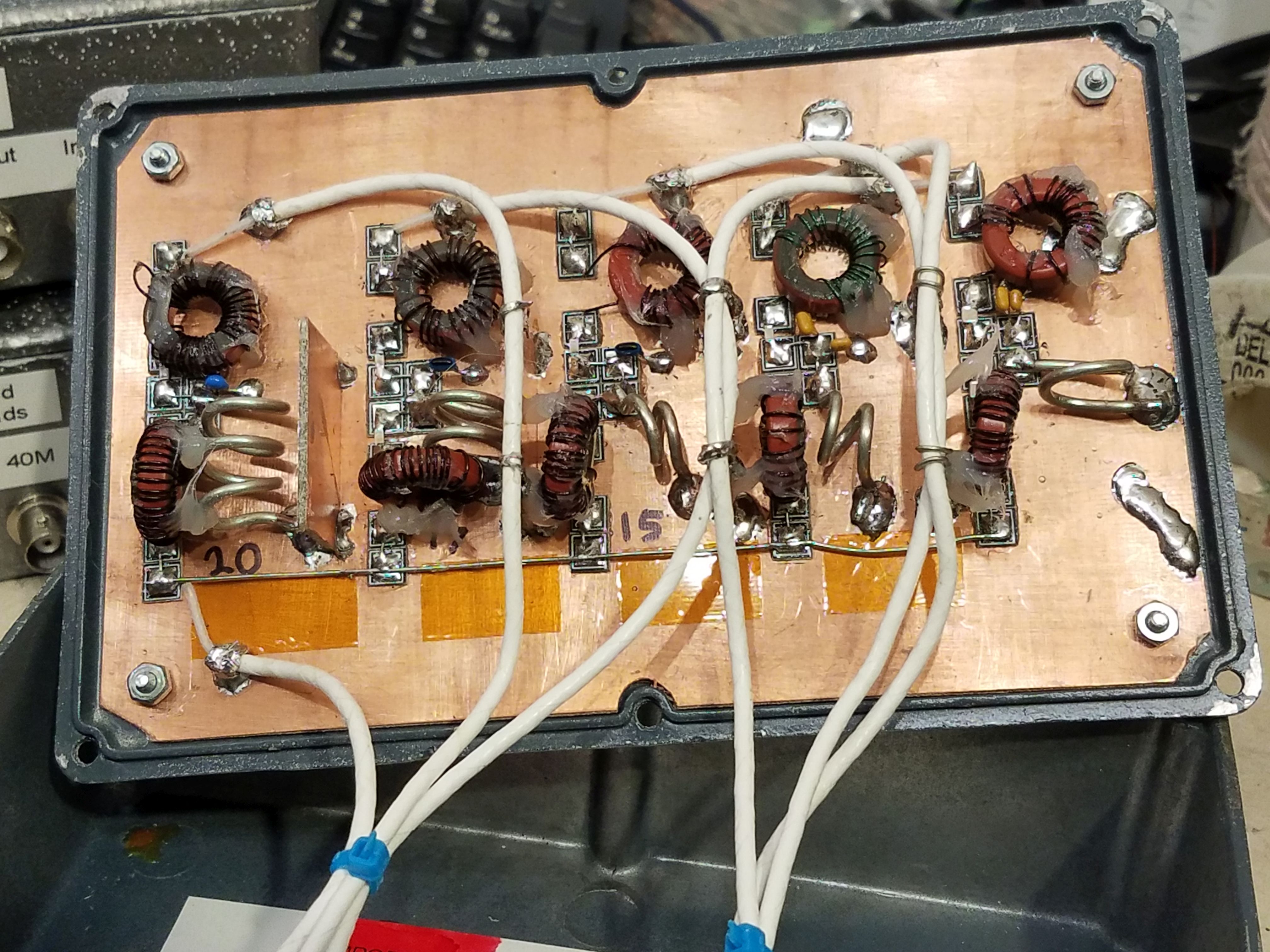
Passive multi-port band-pass filter:

What follows are tables of suggested component values for different types of multi-band combiner/filters.  These filters are intended for specific frequency operation, but are generally likely to be wide enough to allow the complete coverage of the relevant amateur band with good results.

The data below includes options that could include adjacent WARC bands (or 60 meters) as desired - but 12 meters, due to its relative "closeness" to 10 and 15 meters - is not included as this would require insertion loss - using practical construction methods - well over 2 dB.  

You may pick and choose the values from the table below to construct filters for the bands as desired.  Two tables are included below:  The upper table has values calculated to attain 25dB of attenuation at the center frequency of the noted adjacent bands and the lower table has values calculated for 30 dB.  As expected, two parameters lead to higher insertion losses:
Filter topology:

These filters are series-input N=3, meaning that there are three pairs of L/C components to provide the band-pass filtering:  The series L/C on the inputs and outputs allows them to be connected in parallel with minimal interaction.  A complexity of N=3 was chosen to reduce component count, but this also means that the "Q" of the sections is a bit on the high side to attain the desired attenuation so careful attention must be paid to the layout (e.g. good, solid ground plane) and quality of the components (e.g. silver mica or NP0/C0G ceramic capacitors).  

The diagram below shows the nomenclature for the individual filter sections, and how several filters may be connected on a common bus to split and filter signals for receive - or to combine several transmitters on different frequencies.

The top section ("Band 1") represents a single section, and as the additional sections are added, they would be connected to the "Common port" as depicted with the common bus along the left side:  The Line is showed disconnected in the figure below to reinforce the fact that they should be tested individually as they are built and connected together ONLY once this is done.

General diagram of filter and sections

For a "Window" filter:

A "Window" filter is that in which one wishes to pass only certain portions of frequency bands from a common source - and then combine the filtered signal back to a common bus, simply connect together the "output" lines (to the right of C3 in each section).

An example where this might be used is for a broadband receiver (e.g. KiwiSDR, RX-888, etc.) may be subject to overload from the entirety of signals impinging on it - but only certain frequency ranges (e.g. amateur bands) are of interest.

This same method could also be used to filter/connect several different antennas (e.g. those designed for different frequencies) to a common bus/receiver.


For nominal 25dB isolation to adjacent band:

Description L1 C1 L2 C2 L3 C3 Approx. Calculated Insertion Loss
10M (no 12M) CF=28.1MHz 730nH 31pF 48nH 562pF 729nH 31pF 1.0dB
15M with 17M  CF=21.1MHz 2.0uH 24pF 25nH 2110pF 1.7uH 29pF 0.8dB
15M (no 17M)  CF=21.1MHz 1.74uH 35pF 51nH 1196pF 1.5uH 39pF 0.7dB
17M (with 20M and 15M) CF=18.1MHz 2.4uH 34pF 27nH 2926pF 4.1uH 20pF 0.9dB
20M with 30M and 17M  CF=14.1MHz 3.2uH 42pF 88nH 1599pF 3.1uH 45pF 0.7dB
20M (no 17M or 30M)  CF=14.1MHz 2.1uH 67pF 165nH 904pF 2.0uH 69pF 0.3dB
20M with 30M (no 17M)  CF=14.1MHz 2.4uH 49pF 110nH 1047pF 2.4uH 50pF 0.5dB
30M (with 40M and 20M)  CF=10.125MHz 3.0uH 85pF 96nH 2641pF 2.6uH 97pF 0.4dB
40M with 80M and 30M (no 60M)  CF=7.1MHz 3.6uH 170pF 201nH 2915pF 3.1uH 205pF 0.4dB
40M with 80M (no 30M or 60M)  CF=7.1MHz 2.4uH 194pF 310nH 1454pF 2.1uH 210pF 0.3dB
40M with 60M and 30M  CF=7.1MHz 3.8uH 117pF 103nH 4612pF 3.9uH 114pF 0.6dB
80M with 40M (no 60M or 160M)  CF=3.55MHz 4.4uH 587pF 1.1uH 2452pF 3.7uH 750pF 0.2dB
80M with 40M and 160M (no 60M)  CF=3.55MHz 5.3uH 350pF 618nH 2907pF 3.7uH 477pF 0.25dB
80M with 160M and 60M  CF=3.55MHz 6.1uH 432pF 520nH 4682pF 7.0uH 366pF 0.35dB
160M with 80M  CF=1.82MHz 7.9uH 1327pF 2.1uH 5095pF 8.2uH 1246pF 0.3dB


For nominal 30dB isolation to adjacent band:


Description L1 C1 L2 C2 L3 C3 Approx. Calculated Insertion Loss
10M (no 12M) CF=28.1MHz 1.5uH 20pF 34nH 890pF 1.5uH 20pF 1.2dB
15M with 17M  CF=21.1 MHz 3.0uH 17pF 22nH 2396pF 1.9uH 24pF 1.5dB
15M (no 17M)  CF=21.1 MHz 2.2uH 27pF 46nH 1327pF 1.9uH 31pF 0.5dB
17M (with 20M and 15M) CF=18.1MHz 2.5uH 37pF 23nH 3495pF 4.2uH 20pF 1.2dB
20M with 30M and 17M  CF=14.1MHz 3.0uH 46pF 49nH 2744pF 3.4uH 40pF 0.7dB
20M (no 17M or 30M)  CF=14.1MHz 2.1uH 63pF 112nH 1268pF 2.4uH 57pF 0.4dB
20M with 30M (no 17M)  CF=14.1MHz 2.6uH 47pF 77nH 1536pF 2.7uH 44pF 0.5dB
30M (with 40M and 20M)  CF=10.125MHz 4.2uH 60pF 97nH 2632pF 3.5uH 74pF 0.5dB
40M with 80M and 30M (no 60M)  CF=7.1 MHz 5.3uH 129pF 349nH 1900pF 4.9uH 146pF 0.45dB
40M with 80M (no 30M or 60M)  CF=7.1MHz 3.2uH 159pF 444nH 1121pF 3.4uH 149pF 0.35dB
40M with 30M and 60M  CF=7.1MHz 4.5uH 99pF 100nH 4761pF 6.0uH 75pF 0.9dB
80M with 40M (no 60M or 160M) CF=3.55MHz 4.4uH 684pF 933nH 2974pF 5.2uH 539pF 0.25dB
80M with 40M and 160M (no 60M)  CF=3.55MHz 4.5uH 432pF 565nH 3460pF 6.0uH 329pF 0.3dB
80M with 160M and 60M  CF=3.55MHz 7.2uH 344pF 416nH 5599pF 10.3uH 222pF 0.5dB
160M with 80M  CF=1.82MHz 10.4uH 879pF 1.71uH 5653pF 11.1uH 818pF 0.25dB


Construction notes - PLEASE READ!


The picture below shows one possible construction method:

As-built multi filter

About the filter in picture:


Comments on tuning the filters  You had better read this, too!


For tuning the filters, it is recommended that they be tuned individually as follows:

More to be added!

CT20230405


Northern Utah WebSDR landing page