Nothern Utah WebSDR Logo - A skep with a Yagi Northern Utah WebSDR
Receiving equipment
RF Distribution and filtering

Figure 1:
Block diagram of the various RF signal paths at the Northern Utah WebSDR from the TCI-530
omnidirectional antenna and from the VLF antenna system.
The signal paths and receive equipment for the 6 and 2 meter bands is not shown.
See below for the signal path from the LP-1002 log periodic beam.
Click on the image for a larger version.
Block diagram of the TCI-530 signal path with the AM BCB splitter-amplifier and low HF splitter
RF Distribution and Filtering from the TCI-530 Log Periodic omnidirectional antenna:

There are two antennas used for HF reception on site - and this portion describes that associated with the TCI-530 omnidirectional log periodic antenna which is designed for transmit coverage from 3 to 30 MHz, but is used for reception down to about 400 kHz:  Below this frequency, a separate active antenna is used as noted below.

To achieve our goal, we decided from the outset that we should make the receive system capable of receiving on every HF band, but to do this we'd need a lot of outputs, as in:
  1. 2200 meters
  2. 630 meters
  3. 160 meters
  4. 80/75 meters *
  5. 60 meters 
  6. 40 meters *
  7. 30 meters
  8. 20 meters *
  9. 17 meters
  10. 15 meters *
  11. 12 meters
  12. 10 meters *
* - Multiple outputs connections needed if narrow-band "Softrock" type receivers sound cards are used.

One way that we could have done this would have been to use conventional transformer-type splitters to divide the signal and the simplest way  - to divide it by 16 - would have yielded about 20dB of insertion loss - and the above doesn't take into account that for many of the HF bands (those marked with an asterisk) we'd need several antenna connections to feed enough receivers to cover many of the bands if we use "high performance" receivers that can provide only up to 192 kHz of coverage.

With this method there are two other problems with which one must contend:
While it is certainly possible to make this scheme work, there's another method:  Use a "diplexer" type splitter.

Signal distribution strategies:

A "diplexer" type splitter minimizes the insertion loss by selectively "picking" various bands from a common bus.  By having a filter that pulls only narrow ranges of frequencies of individual amateur bands - but leaves the other frequencies alone - we can put several of these same filters on the same bus and instead of 15-20dB of insertion loss from cascaded splitters we can easily keep the loss down to single digits of dB.  The idea is simple - but we decided early on that this wasn't going to be our only approach.

The receive signal path (from the antenna) was designed from the outset to be both versatile and high-performance with the following goals in mind:
To accomplish this several modules were built, depicted in Figure 1:
Figure 2:
Top:
 The schematic of the "Splitter/AM BCB Reject/Amplifier" module.
Upper Middle:  The schematic diagram of the "Low HF Splitter" module.
Lower Middle: The diagram of the "High HF Splitter" module.
Bottom:  The diagram of the splitter/low-pass/BPF module for RTL-SDR receivers.
Click on an image for a larger version.
The AM BCB filter/splitter module schematic
The low HF splitter schematic
The High HF splitter schematic
The BPF/LPF/Attenuator for RTL-SDR receivers
Also depicted in Figure 1 is another module, connected to the output of the Splitter/BCB filter module, that feeds two RTL-SDR dongles.  As required for best performance, these devices should have their inputs filtered to pass only the frequency range of interest and the diagram shows this being done:  A 3 MHz low-pass to accommodate the receiver that tunes 630 through 160 meters (including the AM broadcast band) and a 4.5-7 MHz band-pass filter for the receiver that tunes the 60 Meter SWBC and amateur frequencies and the 49 meter SWBC bands.  This module also has adjustable attenuators that are set to the "sweet spot" - that is, just enough attenuation to prevent serious overload by strong signals and not so much attenuation that weak signals cannot be heard.

At first glance it might seem that placing a splitter at the input of the system and losing 3dB "off the top" would be a bad idea, but this ignores a fundamental truth about HF signal reception:  As noted above, the HF frequency range is very noisy, which means that we can tolerate quite a bit of loss (and incur a rather high system noise figure) in front of our receivers without actually degrading overall system sensitivity.  This simple fact can be demonstrated by connecting a highly-sensitive receiver to a full-size receive antenna and experimenting with a step attenuator and noting the amount of attenuation required to quash the atmospheric noise.  Typically this value, on an antenna devoid of man made noise under normal "quiet", HF conditions, implies that an acceptable system noise figure ranges from about 45dB at 160 meters, decreasing to 24 dB at 20 meters and 15 dB at 10 meters. 5  What this means is that even if we end up with 6 dB of added loss in our HF signal path through splitters and filters, it is still possible to recover the natural noise floor on at 10 meters without requiring any sort of exotic, low-noise amplification.

Comments on Figure 1:

Band-pass filter/attenuator modules for the RTL-SDR dongles:

If you've been reading along you'll already know that it is imperative that RTL-SDR dongles used on HF (or anywhere else) MUST have filtering of some sort on their RF input:  It's not just the signals in the frequency range of interest that are "seen" by the A/D converter when operating in "Direct" mode, but all signals at all frequencies.  In order to maximize what (little) signal handling capability these devices have, it is required that effective filtering be used.

As mentioned previously, one must also provide a means of adjusting the RF single levels being applied to the input of an RTL-SDR dongle, trying to find the "sweet spot" where there is enough attenuation to prevent overload by strong signals yet there is enough overall system gain to receive weak signals.  This balancing act can be quite tricky - particularly when one considers the number of signals and that the strength of those signals vary dramatically between day and night.  At the Northern Utah WebSDR, we are "fortunate" in that there are no strong shortwave broadcast stations "nearby" that beam their signal in our direction - but you are in Europe and eastern North America, the story can be quite different, with multi-hundred kW stations being beamed in your direction and only one "hop" away!

The diagram of the filter module is shown in the bottom of Figure 2 and enough information is provided for several options.  A two-way splitter is depicted on the diagram to allow the feeding of two separate RTL-SDR dongles and their filters while off to the side, a 3-way splitter is shown.  If a 4-way splitter were required, one would cascade a pair of 2-way splitters after a single 2-way splitter (for a total of 3 splitters) - but as noted on the diagram, each set of splitters would incur a loss of about 3.5dB.  If no splitting is required, these would simply be left off.

The upper portion of this diagram also depicts a filter suitable for use on the AM and 160 meter bands.  The left-hand portion is a 500 kHz high-pass filter that removes potentially strong LF signals and noise while the right-hand portion cuts off signals above approximately 2.5 MHz.  On the output of the filter is a very simple attenuator that is used to adjust the signal levels being fed to the RTL-SDR.  Using a single potentiometer, this attenuator is not a "constant impedance" device, but it does provide an "approximate" load for the filters to preserve their general characteristics.  In reality, the RTL-SDR really doesn't care about its input source impedance, and at HF frequencies with fairly short cables, it's not all that important, either!

Also depicted in the diagram is a band-pass filter along with the same attenuator seen in the low-pass portion.  The design of this band-pass filter is one that is "borrowed" from the QRP Labs web site, from their "Band Pass" filter products (a link to that page is here).  In the assembly manual, which may be found on that web page, you will find a technical description of the filters (along with some representative band-pass plots) that provide enough information for you to build your own filters.  If you wish, you may buy these modules in kit form and I can recommend that any of the kits sold by QRP Labs are worth getting!  If you plan to cover a frequency range that isn't shown - such as a shortwave broadcast band - these filters can be tuned/modified from the nearest amateur band.

As noted previously, these RTL-SDR modules are somewhat "deaf" so it is likely that some sort of RF amplifier will be required - particularly to provide the bit of "excess" signal that one would need to be able to adjust levels downward again:   Any of the 2N5109-based amplifier modules described earlier in this page will fit the bill nicely.

Finally, remember that RTL-SDR dongles in the "direct" mode aren't really all that well-suited for covering the 20 or 10 meter bands owing to the Nyquist limitations - and reception on frequencies between these bands (e.g. 17, 15 and 12 meters) will suffer a bit owing to decreased sensitivity and the increased tendency for spurious signals to appear.  On 20 through 10 meters one would be better off using a dongle that includes an "up converter" - or build a simple "down converter":  In any case you will always want to use a band-pass filter in front of the RTL-SDR dongle's receive system to maximize its performance!


RF Distribution and Filtering from the LP-1002 Log Periodic Beam antenna:
Figure 3:|
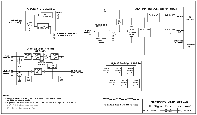
Signal path diagram for the LP-1002 Log Periodic beam antenna.
Not shown is a lightning arrestor on the "HF Antenna" input.
Click on the image for a larger version.

Block diagram of the LP-1002 beam signal path with the AM BCB splitter-amplifier and low HF splitter

Also on site is a U.S Antenna Products (formerly "Hy-Gain") LP-1002 antenna.  This is a very large log-period beam antenna designed for coverage from 6 through 40 MHz that is pointed east on a non-rotatable mount and the signal path for this system may be seen in Figure 3.  From the beam to the bottom of the tower is an approximately 80 foot run of 1/2" "Heliax" cable which has a loss of less than 0.4dB at 30 MHz.

At present, the feedline between the antenna tower and the building with the receivers is temporary, consisting of about 150 feet of RG-6 cable laying on the ground:  A permanent feedline is awaiting the equipment needed to bury it underground.

LF/HF Diplexer + HF amp:

At the base of the tower for this antenna is a module that takes the signals from the beam, removes signals above 40 MHz (to remove FM broadcast signals) and filters signals below 1.8 MHz (to remove AM broadcast signals).  This filtered signal path is then amplified using a 2N5109-based amplifier to provide gain to minimize noise figure degradation along the rest of the HF signal path.  The output of the amplifier is then passed through a 1.4 MHz high-pass filter which forms part of a combiner network, mentioned below.

Also provided by this box is an input from the active LF antenna that is mounted on this tower.  The signals from this antenna are low-pass filtered at 1.4 MHz and combined with the HF signals from the beam.  The DC power fed via the coax is used not only to power the LF active antenna, but also the aforementioned HF amplifier.

All inputs contain gas-discharge tubes

LF/HF/DC Coupler/Splitter:

This device is located at the "receiver" end of the feedline from the antenna and it contains a 1.4 MHz high-pass filter to separate the HF signals and a 1.4 MHz low-pass filter to separate the LF signals:  The former are sent to the Input protection/Splitter/BPF Module (described below) and the latter is sent to the LF input of the LF/HF Diplexer unit mentioned above.

Input protection/Splitter/BPF Module:

The RF input to this unit passes through a Mini-Circuits ZFDC-20-3 coupler which, like that used on the TCI-530 system, allows the injection of test signals into the receive system while causing well under 1dB of loss:  This allows the testing and calibration of the receive gear without interrupting the signal path.  Via prior measurement, the amount of overall amplification provided by the amplifier at the antenna is known, allowing the absolute signal level at the antenna terminals to be known.

The input to this module has a 60 volt gas discharge tube to protect against lightning and like the similar unit on the TCI-530, the signal path is immediately split two ways - one going to the narrowband filter system for the individual receivers of the WebSDR and a "wideband" signal path to feed receivers like such as the KiwiSDRs.

The "narrowband" path goes to a diplexer that splits the signals two ways:  A high-pass filter that allows signals above 9.5 MHz to go through, which is then fed to the "High HF Band-Split Module" for 30 meters and up and a 7.6 MHz low-pass filter.  Beyond the 7.6 MHz low-pass filter, a "strong" 6.8 MHz high-pass filter provides signals for the 40 meter band, the high-pass filter offering about 20dB attenuation of the extremely strong 49 meter (6 MHz) shortwave broadcast signals.  The output from 6.5 MHz low-pass filter is for experimental use:  It allows lower-frequency signals that might be intercepted by the beam antenna - even those below the 6 MHz lower limit - to be passed to receivers that might be used in the future.

High HF Band-Split module:

This module is nearly identical to the same-named module used on the TCI-530 signal path described above.  This unit consists of individual band-pass filters that pick their respective amateur bands' frequencies off a common bus:  This approach is taken instead of a signal splitters as it provides lower loss than a simple signal splitter plus it intrinsically provides the needed band-pass filtering for each, individual amateur band.  Because overall system gain is provided at the antenna, there is no amplifier immediately preceding this module as there is in the TCI-530 signal path.


References:

  1. Youngblood, Gerald (July 2002), "A Software Defined Radio for the Masses, Part 1" (PDF), QEX, American Radio Relay League: 1–9
  2. Youngblood, Gerald (Sep–Oct 2002), "A Software Defined Radio for the Masses, Part 2" (PDF), QEX, American Radio Relay League: 10–18
  3. Youngblood, Gerald (Nov–Dec 2002), "A Software Defined Radio for the Masses, Part 3" (PDF), QEX, American Radio Relay League: 1–10
  4. Youngblood, Gerald (Mar–Apr 2003), "A Software Defined Radio for the Masses, Part 4" (PDF), QEX, American Radio Relay League: 20–31
  5. Johnson, Gary, "Measurements on a Multiband R2Pro Low-Noise Amplifier System, Part 2" (PDF)
  6. Reisert, Joe, (November, 1984), "High Dynamic Range Receivers, Ham Radio.  An English translation of part of this article from a Dutch web site may be found here.
  7. Turner, Clint, (March, 2018), "Managing HF signal dynamics on an RTL-SDR receiver"
  8. Farson, Adam, "Antenna and Receiver Noise Figure"

Pages about other receive gear at the Northern Utah WebSDR:
Go to the main "RX Equipment" page.


Additional information:
 Back to the Northern Utah WebSDR landing page