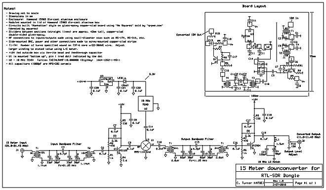
- A 16.384 MHz TCXO was used for the local oscillator and as this
is a standard "microprocessor" frequency and is both inexpensive and
readily available. The 16.384 MHz LO results in 28.0-29.7 MHz
being converted to the range 11.616-13.316.
- The input bandpass filter - a QRP Labs design - covers 28.0-29.7 MHz.
- The output bandpass filter - modified from a QRP Labs design - covers from about 11.5-13.5 MHz.
The RTL-SDR dongle was configured to run at 2.048 Msps with the center
frequency being 28.676 MHz, providing coverage from 27.652-29.700 MHz.
Because of the RTL-SDR's internal 28.8 MHz clock, there is a
moderately strong carrier at this frequency that cannot be avoided.
Addendum:
It was later found to be necessary to add yet
another
RF amplifier after the one on the downconverter's output to bring the
signal level up enough to make the RTL-SDR dongle capable of hearing
the background
(thermal) noise on the 10 and 15 meter amateur bands on the respective downconverters. This amplifier was placed
after the output level adjustment potentiometer
(R10 in Figure 1)
to minimize the amount of signal that this amplifier could see.
Because of the comparative deafness of the RTL-SDR in "direct"
mode, the apparent increase in noise figure by placing the gain control
at that point is irrelevant.
Because of the limited dynamic range of these dongles
(no matter whether you use an upconverter, downconverter or "direct") having such a level control on the input is
absolutely necessary.
Later versions:
After the units described above were built, more were found to be
necessary - but a change was made: Rather than have an output
amplifier transistor as described above, an Analog Devices AD8367
evaluation board was implemented as both an amplifier and AGC - the
latter being to prevent strong signals from overloading the RTL-SDR
when the band is open.
Details on this circuit will be detailed here later.


